What Is a Power Station Generator and How Does It Work?

A power station generator is the working heart of a conventional electricity plant. It converts mechanical energy into electrical energy, usually through electromagnetic induction. Unlike a portable battery unit, it does not store electricity. It produces electricity while a prime mover turns its shaft.

Paul Breeze, an energy specialist and author of Power Generation Technologies, states, “A generator converts mechanical energy into electrical energy.” This simple sentence captures the central idea. However, real equipment is more complicated. A turbine may spin the generator at thousands of revolutions per minute. Steam, water, gas, or diesel engines can provide that motion.

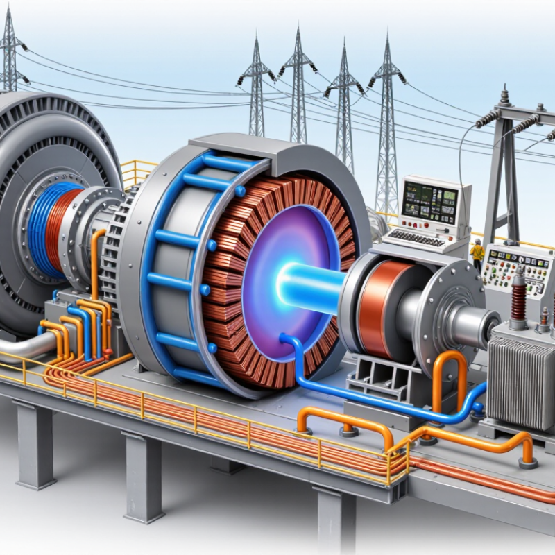
Inside the machine, the rotating rotor creates a moving magnetic field. The stationary stator contains copper windings. As the magnetic field passes across these windings, it induces an alternating electrical current. Transformers then increase the voltage for efficient transmission across long distances. Control systems monitor speed, temperature, vibration, voltage, and frequency.

The process sounds clean on paper.

Real plants are less tidy.

Operators must balance changing demand, mechanical wear, cooling requirements, and grid stability. A small vibration can signal a serious bearing problem. Incorrect synchronization can also damage equipment or disrupt the network. These details are easy to overlook in a simplified diagram.

This article will explain what a power station generator is, how its main components work, and how electricity moves from rotating machinery to the grid. It will also examine efficiency, maintenance, safety, and common generator types. One point deserves reflection: no generator operates alone. Its reliability depends on fuel systems, turbines, protection devices, skilled operators, and disciplined maintenance.
What Is a Power Station Generator and How Does It Work?

Definition and Main Purpose of a Power Station Generator

A power station generator is a machine that converts mechanical energy into electrical energy. Its main purpose is to supply stable electricity for homes, factories, transport systems, and public services. Unlike a storage battery, it produces power continuously while its prime mover operates. The prime mover may be a steam turbine, gas turbine, water turbine, or reciprocating engine. This mechanical force spins an alternator, where magnetic fields induce an electrical current. Transformers then raise the voltage for efficient transmission across long distances.

Reliable operation depends on more than spinning equipment. Operators monitor temperature, vibration, fuel or steam flow, voltage, and frequency from control panels. Protective systems can disconnect faulty sections within seconds. Regular inspections also matter. A loose connection, worn bearing, or blocked cooling passage can reduce output or cause serious damage. In practical maintenance work, small warning signs are often easier to miss than expected. That distinction matters. A simple explanation can also hide the complex balance between generation and grid demand.

Tips: Check the generator’s operating logs before judging performance. Compare vibration and temperature readings with approved limits, not guesswork. Keep cooling paths clear, and arrange qualified inspections at scheduled intervals. Never treat unusual noise or a burning smell as a minor issue. Shut down equipment only under approved procedures, because incorrect isolation can create additional risks.

Key Components and Their Roles in Energy Conversion

A power station generator converts mechanical energy into electrical energy. It is not a single box. The prime mover supplies rotation, while the rotor creates a moving magnetic field. The stator contains copper windings, where voltage is induced as magnetic flux changes. An exciter controls the rotor’s magnetic strength. Small adjustments matter.

Inside a thermal station, fuel heats water and produces steam. The steam turns a turbine, and the turbine drives the generator shaft. Hydroelectric stations use moving water instead. Wind facilities use aerodynamic torque. The conversion path changes, but the generator’s electromagnetic role remains similar. A transformer then raises voltage for efficient transmission. Switchgear isolates faults, while sensors monitor temperature, vibration, speed, and current. Cooling and lubrication systems protect components during sustained operation.

The U.S. Energy Information Administration reports that natural-gas combined-cycle plants can exceed 60% thermal efficiency under suitable conditions. Conventional steam plants are typically less efficient. The difference comes from recovering heat more effectively. The International Energy Agency’s Electricity 2024 report projects global electricity demand to grow by about 3.2% annually through 2026. That growth increases pressure on generators, transformers, and grid controls. Real plants are less tidy than diagrams. A clean efficiency figure can hide part-load losses, aging insulation, and cooling limits. Operators learn this through vibration trends and maintenance records, not theory alone. A generator may still run. It may not run well.

What Is a Power Station Generator and How Does It Work? – Key Components and Their Roles in Energy Conversion

System Area Key Component Primary Role Energy Conversion or Control Function Typical Technical Information
Energy Source Fuel System Stores, filters, and supplies fuel to the engine. Delivers chemical energy that will be released through combustion. Common fuels include diesel, natural gas, gasoline, and biofuels; fuel choice affects emissions, storage, and operating cost.
Mechanical Drive Prime Mover or Engine Converts fuel energy into rotational mechanical power. Combustion produces high-pressure gases that move pistons or drive a turbine shaft. Reciprocating engines are common for backup and distributed generation; gas turbines are often used for larger, high-speed applications.
Mechanical Drive Crankshaft or Turbine Shaft Transfers torque from the prime mover to the generator. Carries rotational mechanical energy into the electromagnetic conversion stage. Rotational speed is selected to maintain the required electrical frequency, such as 50 Hz or 60 Hz.
Electrical Conversion Alternator Produces alternating electrical current. Uses electromagnetic induction: a rotating magnetic field induces voltage in stationary windings. Normally contains a rotor and stator; output voltage depends on design, excitation, speed, and load.
Voltage Regulation Automatic Voltage Regulator Maintains the generator terminal voltage within a specified range. Adjusts excitation current in response to voltage changes and load conditions. Helps protect connected equipment from excessive voltage variation.
Frequency Control Governor and Speed Controller Controls engine or turbine speed as electrical demand changes. Adjusts fuel or steam flow to balance mechanical input with electrical load. Stable rotational speed is essential for maintaining the rated frequency of the power system.
Cooling Radiator, Heat Exchanger, or Cooling System Removes heat generated by combustion, friction, and electrical losses. Transfers waste heat to air, water, or another cooling medium. Proper cooling prevents overheating and supports reliable continuous operation.
Lubrication Oil Pump and Lubrication Circuit Reduces friction and wear in moving engine components. Maintains an oil film between contacting surfaces and carries away some heat. Oil pressure and temperature are commonly monitored for preventive maintenance.
Air and Exhaust Air Intake, Exhaust Manifold, and Silencer Provides combustion air and directs exhaust gases away from the engine. Supports efficient combustion and reduces noise and harmful emissions. Filters, catalytic systems, and particulate controls may be used to meet applicable emission requirements.
Power Conditioning Circuit Breaker and Switchgear Connects, disconnects, and protects the generator and electrical load. Interrupts fault current and provides controlled power distribution. Protection may include overcurrent, short-circuit, earth-fault, and under- or over-voltage functions.
Control and Monitoring Control Panel Displays operating conditions and manages starting, stopping, and alarms. Coordinates electrical and mechanical control signals to keep operation within safe limits. Typical readings include voltage, current, frequency, engine speed, oil pressure, coolant temperature, and operating hours.
Starting System Battery, Starter Motor, or Compressed-Air Starter Initiates rotation of the prime mover. Supplies the initial mechanical energy required before self-sustaining combustion begins. Standby generator systems commonly use batteries and automatic start controls.
Power Output Terminal Output Delivers usable electrical power to a load or grid connection. Transfers generated alternating current after regulation and protection. Output may be single-phase or three-phase; apparent power is commonly stated in kVA, while real power is stated in kW.
Performance Electrical Efficiency Indicates how much input fuel energy becomes useful electrical energy. Accounts for combustion, mechanical, thermal, and electrical losses. Overall electrical efficiency varies by technology and load; reciprocating engine generators commonly operate below the efficiency of combined-cycle plants.
Operating Modes Standby, Prime, and Continuous Operation Defines how frequently and for how long the generator may be operated. Matches generator loading and maintenance requirements to the intended duty cycle. Standby operation supports emergency backup; prime operation permits variable loads; continuous operation is designed for sustained demand.

How Mechanical Energy Becomes Electrical Power

What Is a Power Station Generator and How Does It Work?

A power station generator converts mechanical energy into electrical power. The process begins when a prime mover turns a shaft. This mover may be a steam turbine, water turbine, gas turbine, or large engine. The rotating shaft drives a rotor inside an alternator. As the rotor spins, its magnetic field moves through copper windings. This motion induces an electric current. That is electromagnetic induction in practical form.

The machine does not create energy from nothing. It changes one form into another, while some energy becomes heat, vibration, and sound. Operators monitor shaft speed, temperature, voltage, and vibration during operation. A small change can signal bearing wear or an electrical fault. In real facilities, stable output depends on careful cooling, insulation, lubrication, and maintenance. The explanation sounds simple. The engineering is not.

Tips: Keep air inlets and cooling paths clear. Check unusual noise or rising temperature early. Never touch internal parts during operation. Follow approved procedures and use qualified technicians for testing. It is also wise to record operating readings, because trends often reveal problems before an alarm appears. My view is that generator efficiency should not be judged by output alone. Reliability, safe operation, and controlled heat loss matter just as much.

Fuel Sources, Generator Types, and Operating Systems

What Is a Power Station Generator and How Does It Work?

A power station generator converts mechanical energy into electrical energy. Its fuel source drives this process. Natural gas and diesel commonly power reciprocating engines or gas turbines. Coal and biomass can heat water, creating steam for a steam turbine. Hydroelectric stations use flowing water instead of combustion. Each source changes the plant’s cost, emissions, maintenance needs, and response speed.

Generator types suit different operating demands. Reciprocating units start quickly and support backup or peak loads. Gas turbines provide high output with relatively compact equipment. Steam turbines often serve large, steady-load stations. Inside the generator, a rotating magnetic field induces voltage in stationary windings. Operating systems then control speed, voltage, cooling, lubrication, and fuel delivery. Protection relays disconnect faulty equipment within fractions of a second. Synchronization must match voltage, frequency, and phase before connection to the grid. Small errors can cause severe mechanical stress.

Tips: Check fuel quality, ventilation, and coolant levels regularly. Keep inspection records, even when the unit appears reliable. A clean filter can prevent an expensive shutdown. Do not assume automatic controls remove the need for trained operators. In real facilities, sensors can drift, alarms can be misunderstood, and maintenance schedules may be too optimistic. That uncomfortable gap deserves attention. Testing under realistic loads often reveals weaknesses that idle running hides.

Safety Controls, Efficiency, and Grid Integration

A power station generator converts mechanical energy into electricity through electromagnetic induction. Its turbine turns the rotor, while the stator delivers alternating current. Safety controls keep this process stable. Overspeed trips, low-oil-pressure alarms, high-temperature shutdowns, and emergency stops respond within seconds. Ground-fault relays also detect dangerous current paths. These details matter because a minor sensor failure can become a major outage.

Efficiency depends on load, fuel quality, cooling, and maintenance. The U.S. Energy Information Administration reports that generator heat rates vary significantly across technologies and operating conditions. A unit may perform well at rated output but waste more fuel during frequent cycling. The International Energy Agency’s Electricity 2024 report expects low-emissions sources to provide about half of global electricity generation by 2026. This shift increases the need for flexible generators, fast ramping, and accurate controls. Perfect efficiency claims are misleading. Field conditions punish neat calculations.

Grid integration requires matching voltage, frequency, and phase before connection. Synchronizing relays prevent damaging out-of-phase switching, while automatic voltage regulators support voltage stability. Governors adjust output when system frequency changes. NERC’s 2024 Long-Term Reliability Assessment highlights growing risks from extreme weather, rising demand, and changing generation mixes. Operators therefore need tested protection settings and realistic emergency drills.

Tips: Check alarms before every start. Test emergency stops under controlled procedures. Record fuel use at different loads. Review relay settings after major grid changes. Small data gaps can hide large efficiency losses.